| Preparing the Bleeder Resistors and Bypass Capacitors |
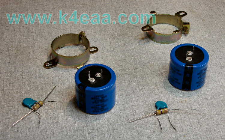 It is easiest to attach the R's and C's to the
Electrolytics before mounting them in the radio. Twist the disk
capacitor's leads around the resistor, and then solder them and clip
off one set of leads.
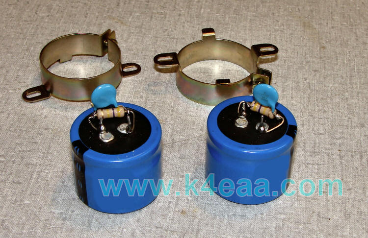 Twist and solder the RC assemblies to the
connections on the electrolytics. Push the wraps to the bottoms
of the terminals to allow room to attach the wires later.
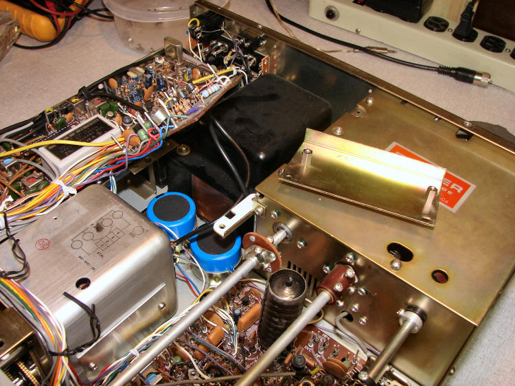 Using the mounting
brackets you removed from the original electrolytics, mount the new
caps onto the chassis being careful to observe polarity in the new
caps. The negative terminal is adjacent to the black line marked
with the "-" symbol. In this TS-520SE, the fixed
channel/AVR board and mounting bracket (sitting on the HV cage) had to
be removed to gain access. On the 530 and 830 models, nothing
blocks access to the capacitor mounting brackets..
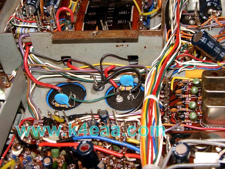 This shows the under chassis wiring of the new HV electrolytics. You can see the corroded bracket above the caps, where one of the original units had leaked electrolyte. It has been cleaned, but still needs some phosphoric acid to stop the corrosion. Only four wires need to be connected. The capacitors are oriented with both negative terminals to the right. The green wire that I used for clarity connects them in series. On the extreme left is the +800V DC connection (red wire). On the extreme right is a connection to ground (black wire). At the center tap between the two capacitors is the remaining wire, that is connected to the "0" tap on the 800VAC transformer winding (red in this case). All models of Kenwood hybrids will be wired the same way. |